How to model soot restructuring
A tutorial on how to simulate soot restructuring using a free and open source tool based on discrete element method (DEM).
Intro
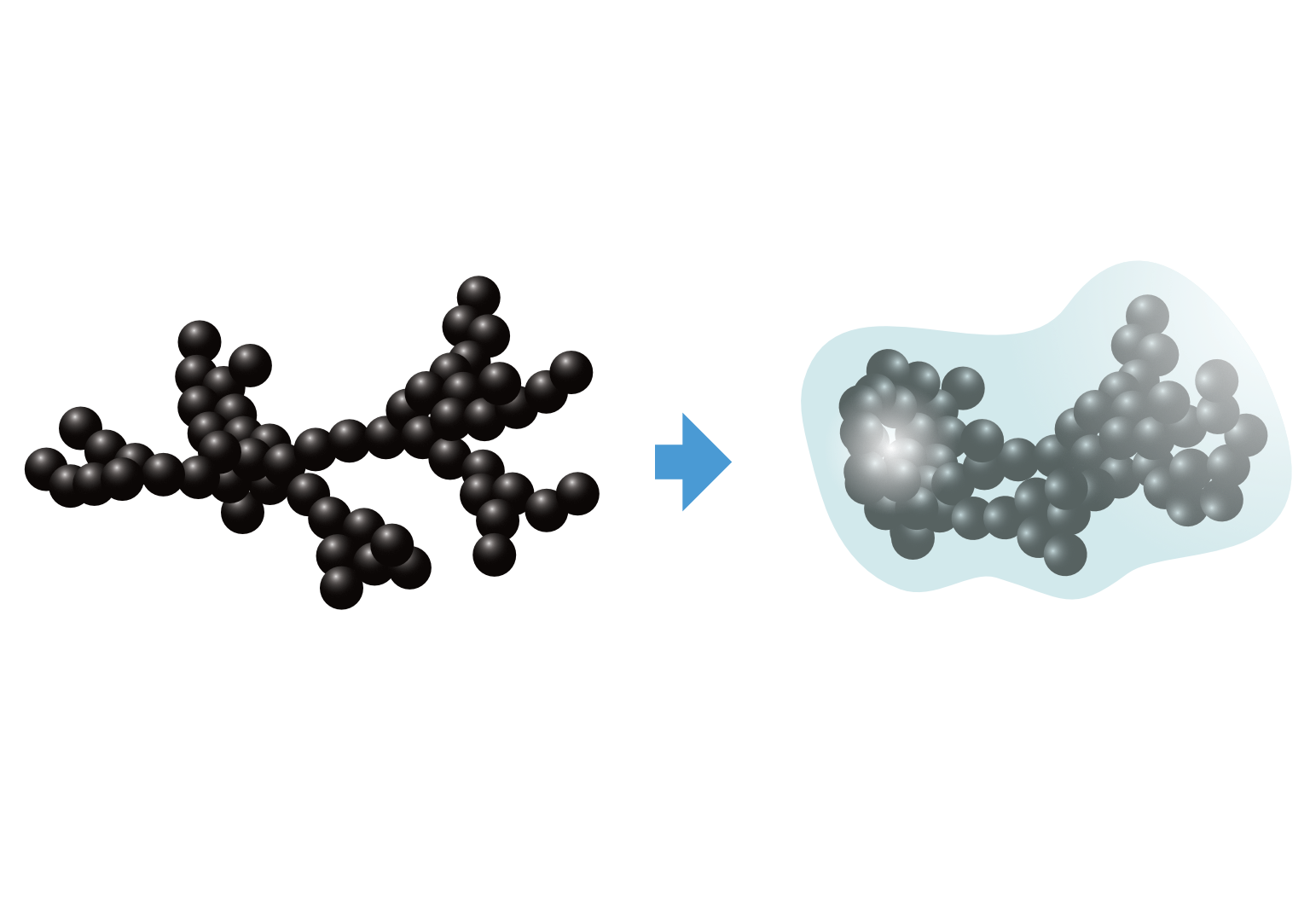
We recently developed a discrete element method (DEM) contact model for mechanics of soot aggregates. Details are available in the preprint. Here, we provide instructions on how to get started using the soot restructuring module that is published with the manuscript.
Part 1: getting started
Download the latest binary for Windows. When you download and extract the archive, a folder named “soot-dem” will be created. Inside that folder, there are two sub-folders: “bin” and “example”. The “bin” folder contains three executables:
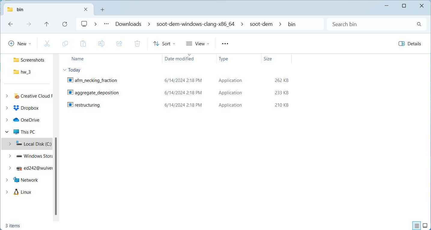
The “restructuring” executable is what we will be using in this tutorial. However, if you try to run it, you will get a warning message claiming that the executable is unrecognized:
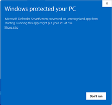
This is because we do not have a code signing certificate to sign the distributed binaries. To bypass this, press “More info” and “Run anyway”:
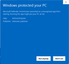
Now, Windows will allow execution of the restructuring.exe. The next step is to add the directory containing the
restructuring executable to your system’s PATH environment variable. Search “path” in the start menu:
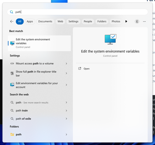
You will be offered to “edit the system environment variables”. Click on this entry. You will be taken to advanced system settings:
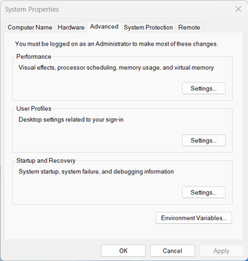
There, click “Environment variables …”:
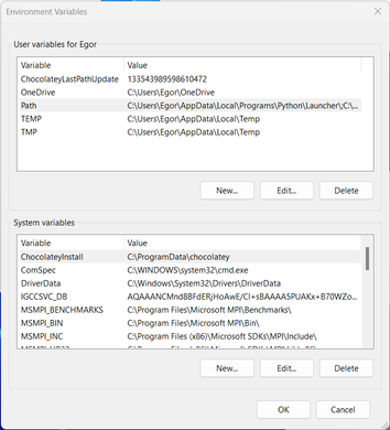
Under “User variables”, double-click “Path” and add the path to the “bin” folder:
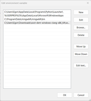
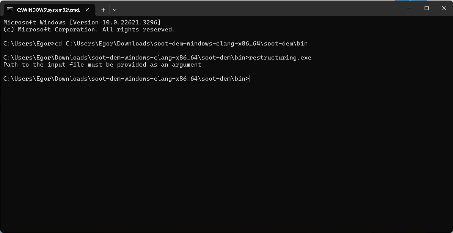
Press “OK” and close the settings window. Now, open the command prompt, type in “restructuring”, and hit enter. If everything went successfully, you should see a message that an input file is required:
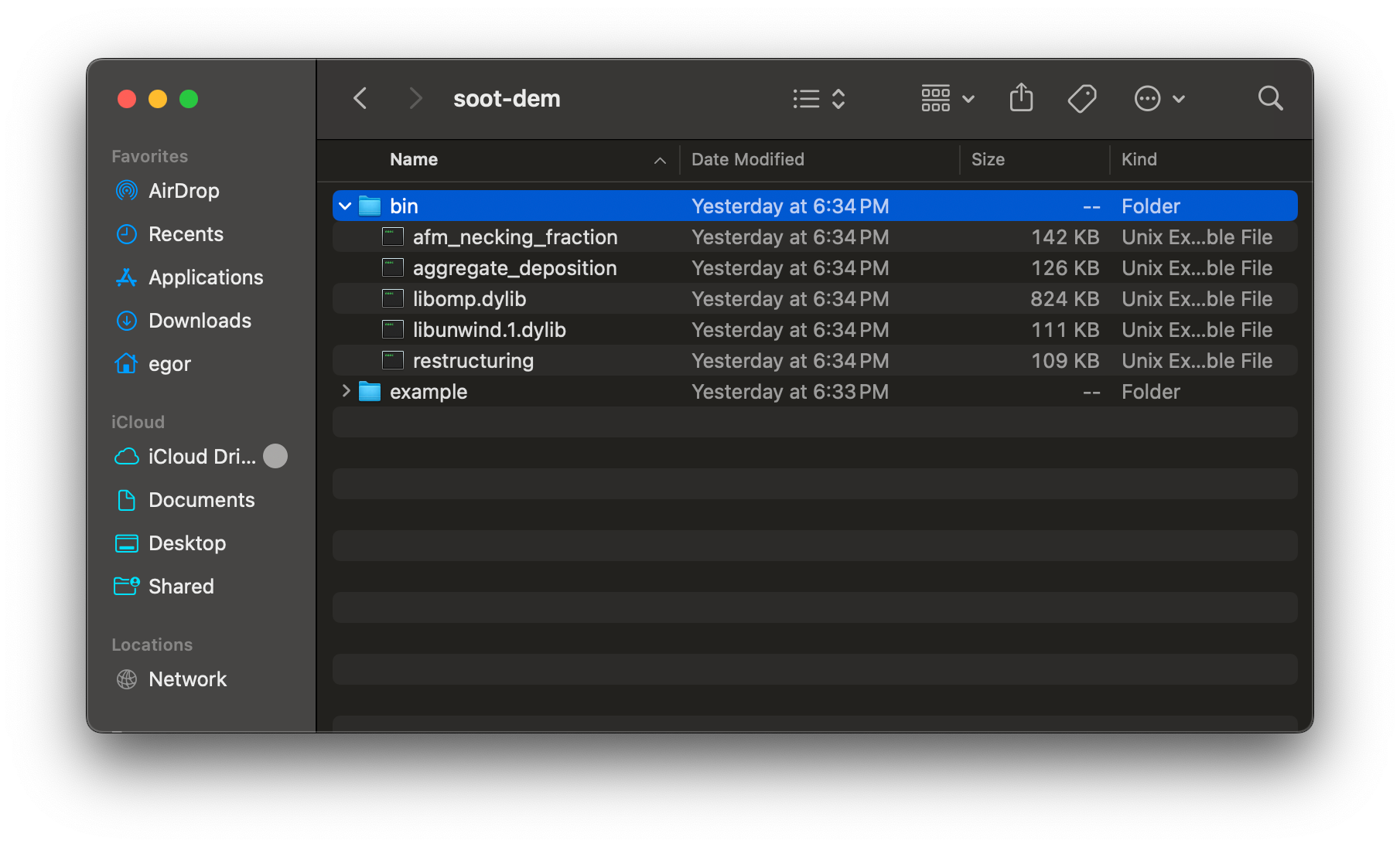
Download the latest binary for macOS. When you download and extract the archive, a folder named “soot-dem” will be created. Inside that folder, there are two sub-folders: “bin” and “example”. The “bin” folder contains three executables and two dynamically linked libraries (.dylib files):
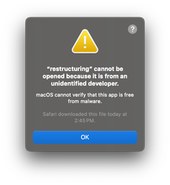
The “restructuring” executable is what we will be using in this tutorial. However, if you try to run it, you will get an error message claiming that the executable is from an unidentified developer:
This is because we do not have a code signing certificate to sign the distributed binaries. To bypass this, open system settings and search for “security”:
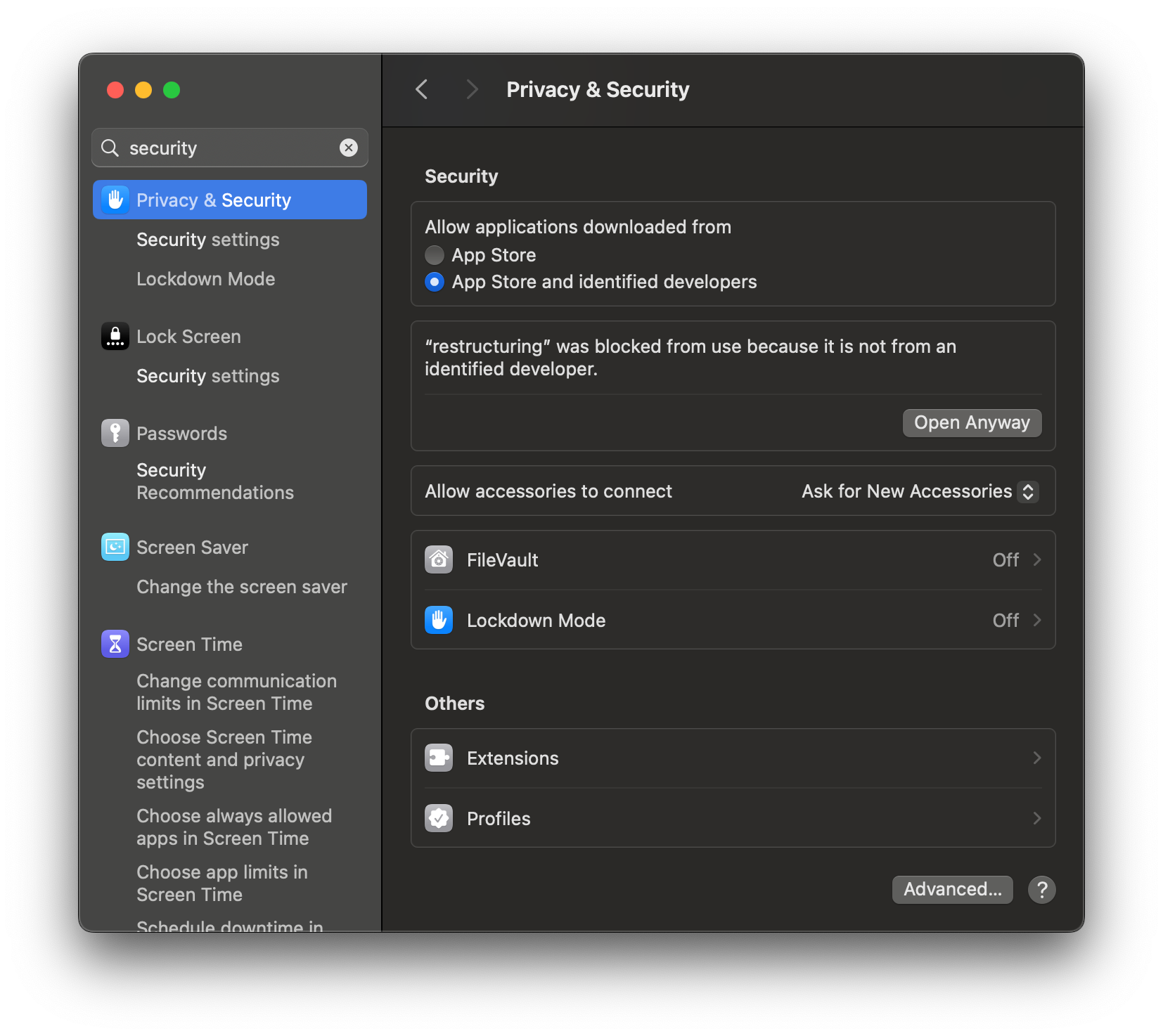
If you scroll down, you will see a section that says that “restructuring” was blocked and an option to open anyway. Press the “Open Anyway” button and enter your password. When prompted, press “Open”:

Now, if you go back to the “soot-dem/bin” folder and try to execute the “restructuring” executable, you should see a command prompt window:
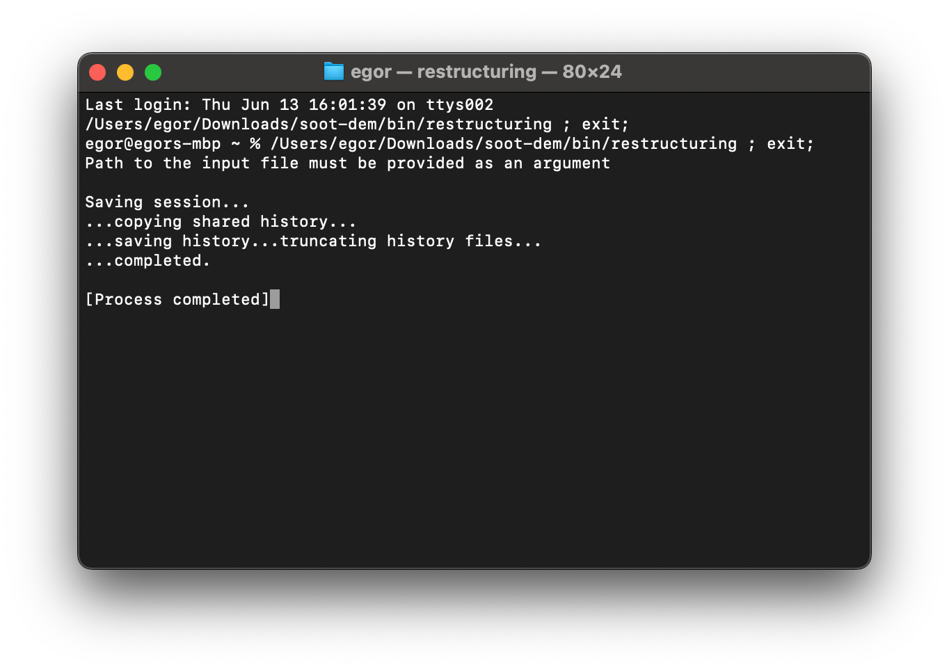
The program should print a message that an input file must be provided and exit. This indicates a successful launch. To add the directory containing the restructuring executable to your system path, run while in the bin directory:
echo export PATH="$(pwd):\$PATH" >> ~/.zshrc
source ~/.zshrc
Clone the git repository:
git clone --recurse-submodules https://github.com/egor-demidov/soot-dem.gitCreate a build directory:
cd soot-dem
mkdir build
cd build
Generate build files using CMake and compile the targets:
cmake ..
cmake --build .
You must be using a C++ compiler that at least supports the C++17 standard. To add the directory containing the restructuring executable to your system path, run while in the bin directory:
echo export PATH="$(pwd):\$PATH" >> ~/.bashrc
source ~/.bashrc
To follow the visualization part of this tutorial, ParaView needs to be downloaded and installed on your system.
Software for generating fractal-like aggregates
To generate fractal-like aggregates to initialize the restructuring simulations, we recommend using the FLAGE tool by Krzysztof Skorupski. However, downloading FLAGE is not necessary for completion of this tutorial, as we provide an example fractal aggregate later on in this article.
Part 2: running simulations
The simulation parameters are described in detail in the manuscript. All parameters need to be provided in either one or multiple input files. Input files should be in the XML format. The path to the main input file must be provided as a command line argument when launching the restructuring module. The main input file can include other input files on the drive, which will also be read by the restructuring executable at launch.
More details about the input file format
Here is an example input file:
<?xml version="1.0" encoding="UTF-8"?>
<simulation type="restructuring">
    <!-- GENERAL SIMULATION PARAMETERS -->

    <!-- Simulation duration -->
    <let id="t_tot" type="real">5e-8</let>
    <!-- Aggregate necking fraction -->
    <let id="frac_necks" type="real">0.7</let>
    <!-- RNG seed (to determine which necks to break) -->
    <let id="rng_seed" type="integer">0</let>
    <!-- Aggregate file type -->
    <let id="aggregate_type" type="string">flage</let>
    <!-- Aggregate file path -->
    <let id="aggregate_path" type="path">../../aggregate_bank/size_150/aggregate_0.xml</let>

    <include>../common_thin_coating_aggregate.xml</include>

</simulation>
An input file has the following features:
- The file starts with the tag
<?xml version="1.0" encoding="UTF-8"?>to indicate the file type and the encoding format - The root XML element is named
<simulation>and, for restructuring simulations, has the required attributetype="restructuring" - The children of the root element are either parameter declarations or include directives
- Parameter declarations come in
<let>elements, which must haveidandtypeattributes.idis the name of the parameter andtypeis the data type of the parameter (one of:string,path,integer,real) - Include directives come in
<include>elements, which contain the relative path to the included XML file as inner text. The path to the included file is relative to the including input file, not the working directory of the user
Here is an example of an included input file:
<?xml version="1.0" encoding="UTF-8"?>
<include_file>

    <include>common_all_simulations.xml</include>

    <!-- Verlet (cutoff) radius for neighbor lists -->
    <let id="r_verlet" type="real">70e-9</let>

    <!-- PARAMETERS FOR THE LIQUID COATING MDOEL -->

    <!-- Maximum magnitude of coating-induced force -->
    <let id="f_coat_max" type="real">1e-9</let>
    <!-- Cutoff distance for the coating-induced force -->
    <let id="f_coat_cutoff" type="real">56e-9</let>
    <!-- Drop rate at cutoff point -->
    <let id="f_coat_drop_rate" type="real">178571429</let> <!-- 10.0/f_coat_cutoff -->

</include_file>
An included file has the following features:
- The file starts with the tag
<?xml version="1.0" encoding="UTF-8"?>to indicate the file type and the encoding format - The root XML element is named
<include_file> - The children of the root element are either parameter declarations or include directives, which follow the same rules as parameter declarations in the main input file. An included file can include more included files
We provide an archive with example input files and a fractal aggregate. These files set up a simulation similar to the restructuring simulations described in the manuscript. Download and extract it. You should end up with the following directory tree:
restructuring_simulations
| common_parameters.xml
| fractal_aggregate.xml
| frac_70
| | restructuring_input.xml
|
| frac_90
  | restructuring_input.xml
The file fractal_aggregate.xml in the root directory contains the geometry of a fractal-like aggregate. The file
common_parameters.xml defines most of the simulation parameters that will be shared by all simulations. Now, we want
to run two restructuring simulations on aggregates with different necking fractions. There are two folders
frac_70 and frac_90 for 70% and 90% necking fractions respectively. In each folder there is a main input file that
defines the necking fraction parameter and includes the input file with common parameters. Having a separate file for
common parameters allows us to avoid repetition of these parameters in multiple input files. Also, say we want to change
the Hamaker constant and re-run the restructuring simulations for all necking fractions. It is as easy as updating the
Hamaker constant value in the common_parameters.xml file, no need to change every single input file for every simulation.
Now, let us run the restructuring simulation on an aggregate with necking fraction of 70%. Open the
restructuring_simulations/frac_70 folder in your command prompt. Set the number of OMP threads to the number of
hardware threads on your CPU (optional; accelerates the simulation):
set OMP_NUM_THREADS=8$Env:OMP_NUM_THREADS=8export OMP_NUM_THREADS=8Now, run the simulation. Assuming that you have added the restructuring executable that was downloaded in Part 1 of
this tutorial to you system path, simply run:
restructuring restructuring_input.xmlAs the parameters are read and processed from the input files and the simulation begins, the following output should appear in your command prompt:
restructuring (part of soot-dem project) by Egor Demidov
Compiler version: GNU 13.2.1
Compiled on: Linux 5.14.21-150500.55.49-default
Built from git commit 54496ab1a284c87c11b7461fea38ff4a847c513d (main)
OMP_NUM_THREADS: 8

REAL PARAMETERS:
    A: 1e-19
    d_crit: 1e-09
    dt: 5e-15
    f_coat_cutoff: 5.6e-08
    other parameters ...

Loaded an aggregate of size 150
Breaking 47 necks ...
Dump: 0/500     KE: 0   P: 0    L: 0    R_g: 1.87881e-07        estimating remaining time ...
Dump: 1/500     KE: 2.47757e-17         P: 1.55244e-32  L: 2.92865e-39  R_g: 1.87822e-07   estimating remaining time ...
Dump: 2/500     KE: 1.01266e-16         P: 4.46102e-32  L: 9.28094e-39  R_g: 1.87651e-07   estimating remaining time ...
Dump: 3/500     KE: 2.39869e-16         P: 8.75937e-32  L: 1.635e-38    R_g: 1.87361e-07   estimating remaining time ...
Dump: 4/500     KE: 3.39696e-16         P: 1.75872e-31  L: 3.23795e-38  R_g: 1.86971e-07   estimating remaining time ...
Dump: 5/500     KE: 3.15377e-16         P: 3.43353e-31  L: 8.93399e-38  R_g: 1.8656e-07    estimating remaining time ...
As the simulation progresses, a folder named run will be created and populated with geometry dump files. Wait till
the simulation is completed before you move on to the next section and visualize your simulation results.
Part 3: creating visualizations
To visualize the restructuring process, open ParaView:
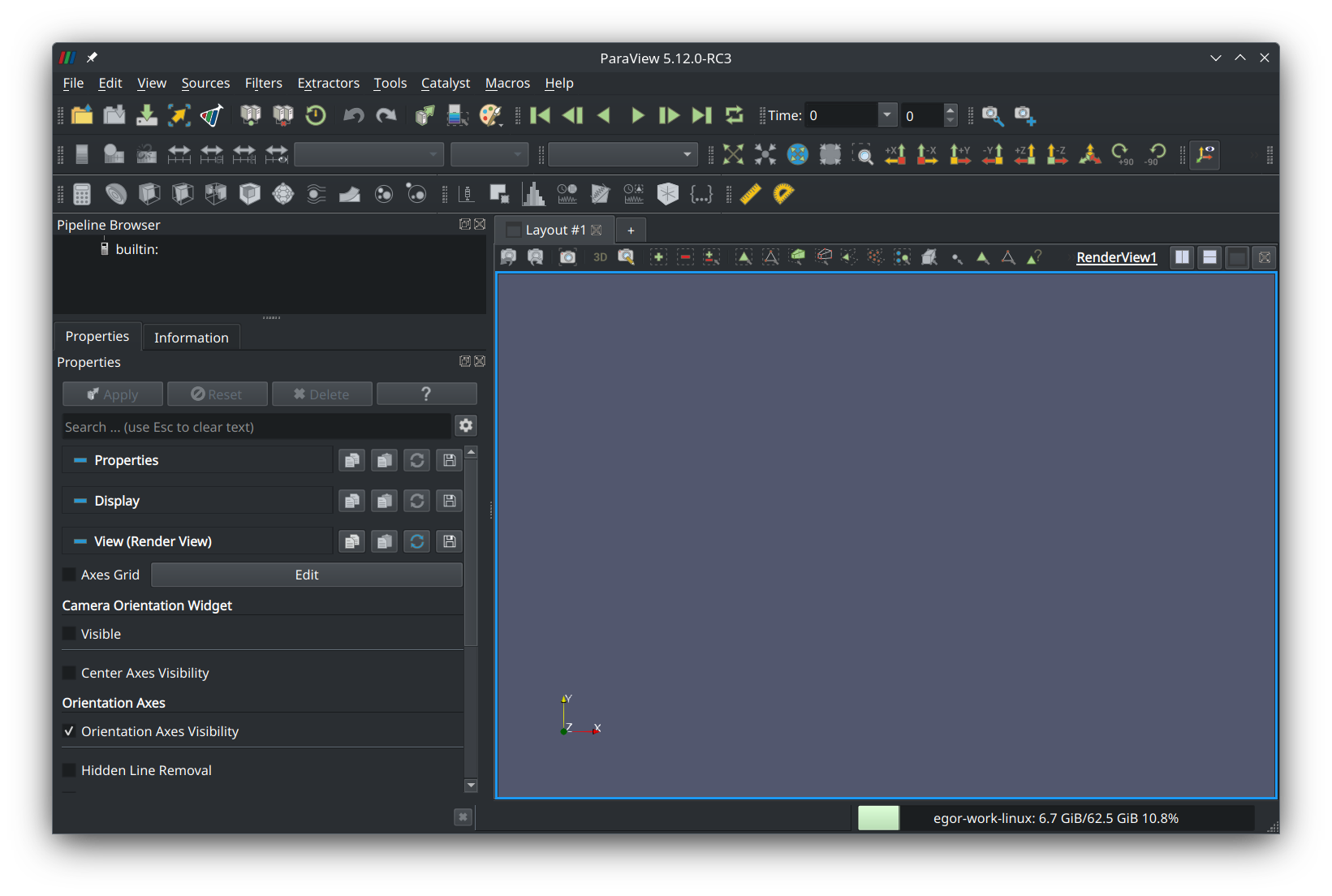
Press the “Open file” button in the left corner of the tool ribbon and navigate to the “run” directory that was created when the simulation was run:
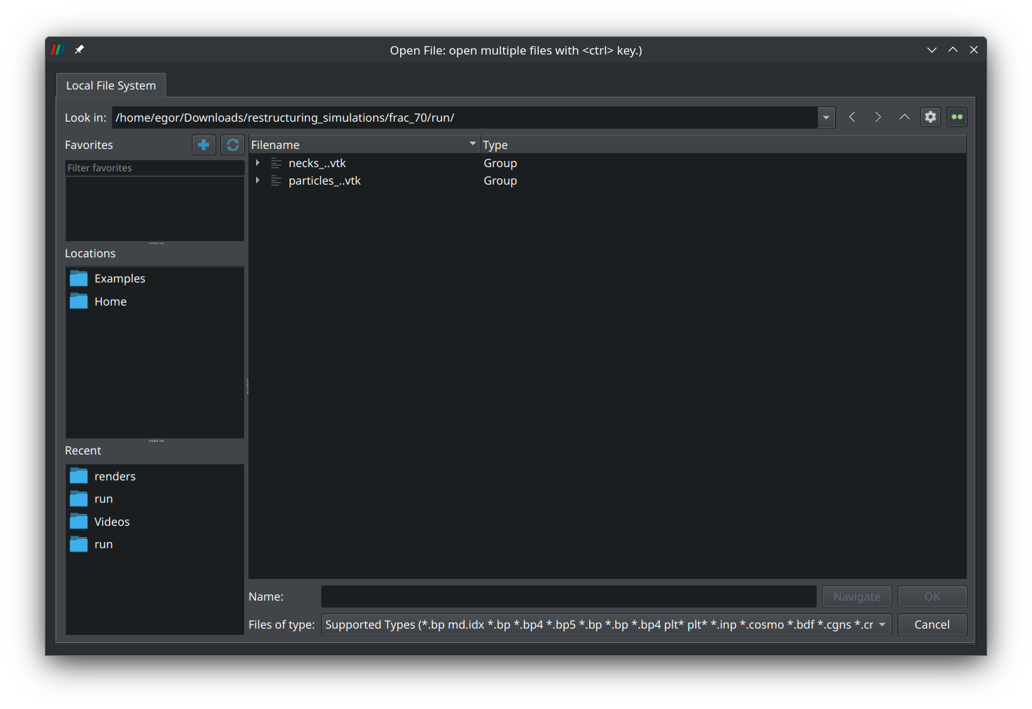
Select the group “particles_..vtk” and press “Ok”. A new entry named “particles_0.vtk*” should appear on the left panel:
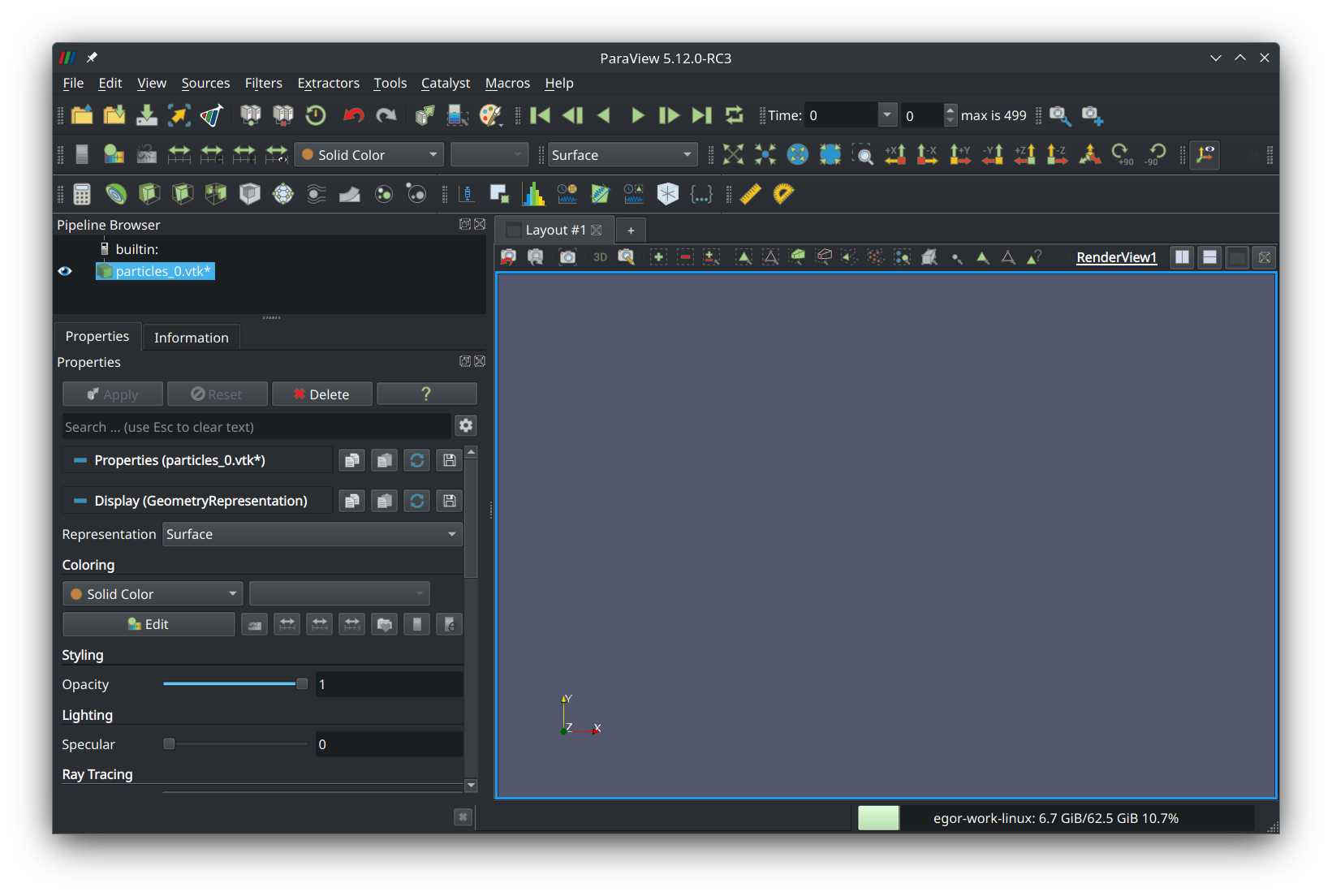
Select it and press “Add glyph” in the third row of the tool ribbon (a button that looks like a globe). In the left panel, a new item named “Glyph1” should appear:
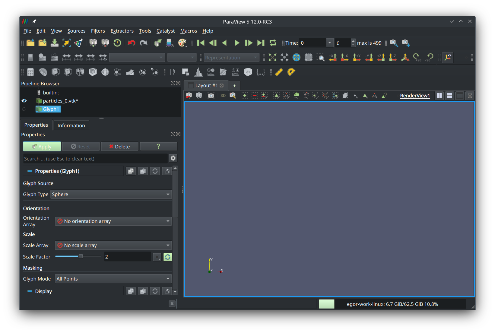
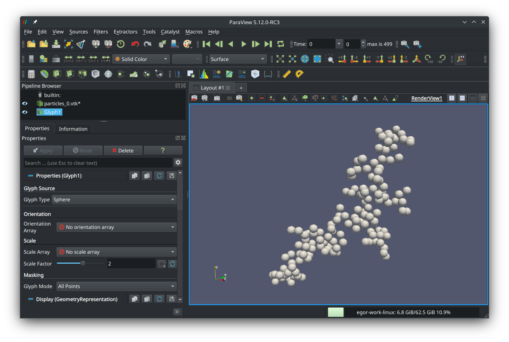
Set glyph type to “sphere”, scale factor to “2”, and glyph mode to “all points”. Press the green button that says “Apply” and you should see your fractal aggregate in the preview panel:
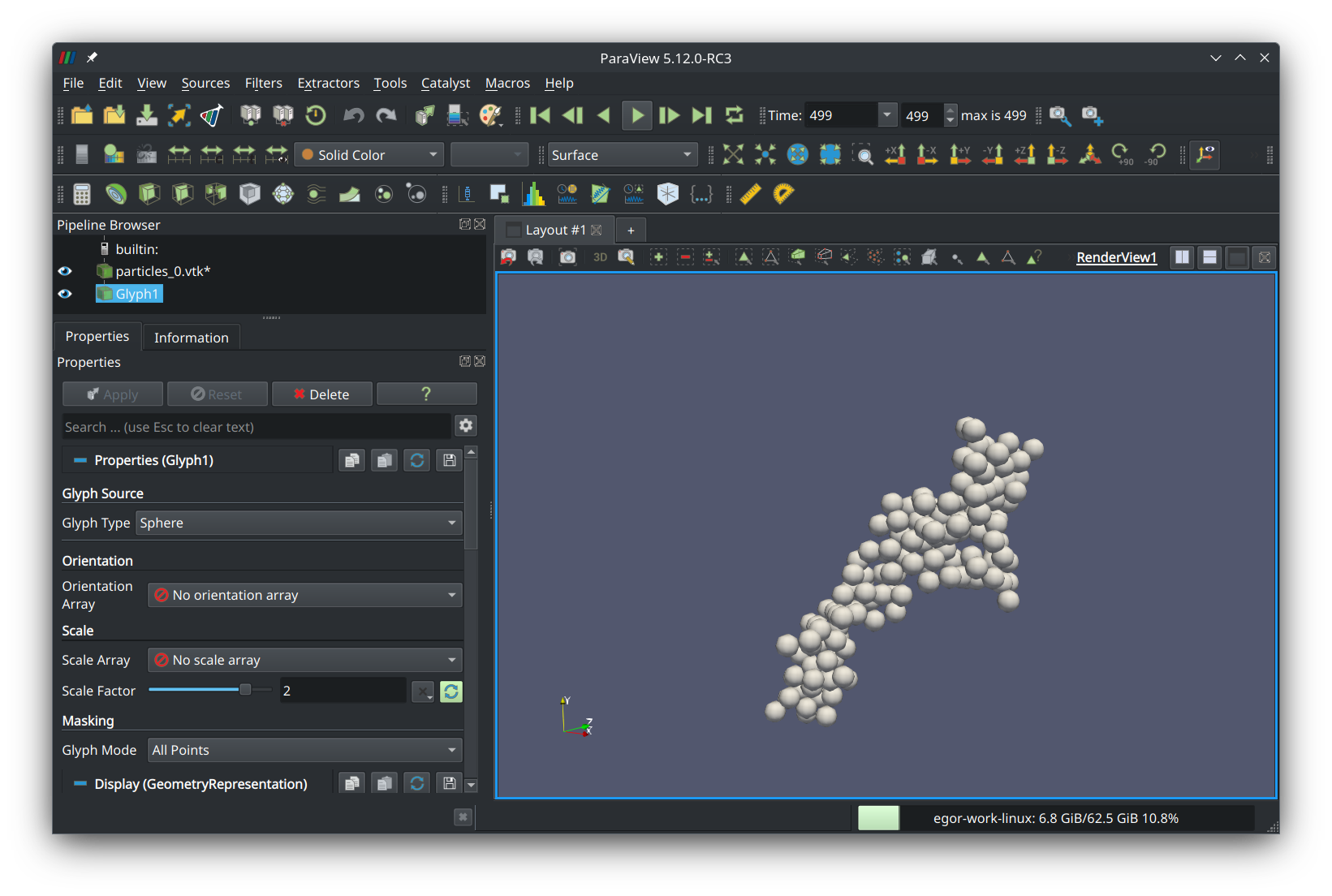
Now, to see the animation, press the green play button in the top ribbon. You should see the aggregate move and become compact:
Summary
In this tutorial, we learned how to run a basic soot restructuring simulation and set up a visualization. The geometry dump files used for the visualization contain x-y-z positions of the primary particles in the aggregate normalized by primary particle radius. Hence, this data can be used to derive other aggregate properties, such as light scattering and extinction cross sections (using DDA or MSTM). We encourage the use of our restructuring module for further study of soot aging. With any questions or concerns, don’t hesitate to reach out to Egor Demidov, ed242@njit.edu.
Attribution
If you use our soot restructuring module for work that will be published, please cite:
@misc{demidov2024discrete,
    title={Discrete element method model of soot aggregates},
    author={Egor V. Demidov and Gennady Y. Gor and Alexei F. Khalizov},
    year={2024},
    eprint={2407.14254},
    archivePrefix={arXiv},
    primaryClass={physics.comp-ph},
    url={https://arxiv.org/abs/2407.14254}
}
Acknowledgement
- Project funded by U.S. National Science Foundation, award #AGS-2222104